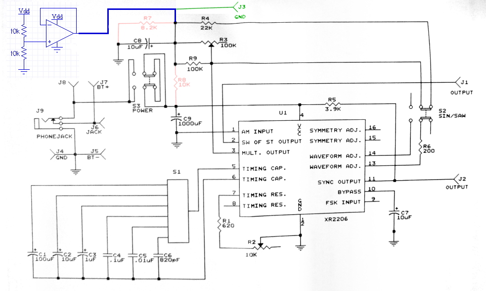
Short story: The FG-500 is a low-cost function generator,
but it has a large DC offset, making it useless for many
applications. To remove the DC offset, replace the resistive divder
formed by R7 and R8 with an op amp to hold the voltage where R7 and R8
meet at 4.5V. Finally, replace the ground connection on the case to
run to the new 4.5V instead of to battery ground. This is shown in the
schematic below:
I used an OPA2134 (the single-ended OPA134 is slightly better for this application, but I didn't have any on hand), but almost any op amp ought to work. Depending on the op amp, C8 may need to be removed, or replaced with a smaller value (if the circuit oscillates, try removing it, and if that helps, try 0.1uF ceramic). Many op amps cannot drive a large capacitive load without oscillations. My OPA2134 didn't have any problems, but YMMV.
I bought an Elenco FG-500K function generator. This is a $35 function generator with advertised specs of 1Hz-1MHz. It runs off of a 9V battery, which is quite nice, since that means it is floating. This means you can put it in series with another source, and it will add to the signal. You can also attach it to other floating circuits without grounding them (which is something I wanted to be able to do for a consulting project designing medical instrumentation), or put it between two arbitrary nodes of a circuit.
I expected a $35 function generator to have issues, and most of those issues I don't mind too much, but there was one show-stopper. The sine wave output by the FG-500 has a large (I didn't measure, but by schematic, about 4.5V) DC offset. The DC offset is much larger than signal amplitude. I needed to fix this to make this function generator useful to me. This page describes what is necessary.
First, solder up an op-amp as a follower of half of the rail, as shown in the schematic above. Almost any op amp capable of running off of 9V with gain-bandwidth above 1MHz should work (depending on op amp, C8 may need to be removed or reduced to ensure stability). I used an OPA2134, which has two op amps, but I didn't use the second one (I prefer not to leave op amps floating, so I connected the second one as shown below):
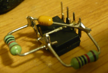
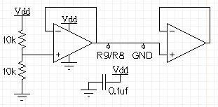
There are tiny jumper wires between the outputs and the negative feedback terminals that are not clearly visible in the photo. An OPA134 would be better, since I wouldn't have a redundant op-amp. Alternatively, I could have used the second op amp to buffer and gain the signal generator output, so that it could have a higher output voltage. I may do that at some point, but for now, the output amplitude is good enough. The capacitor is a 0.1uf ceramic connected between pins 4 and 8 to act as a power supply bypass. A 0.1uf capacitor in parallel with one or both resistors would also have been good form, but I was lazy.
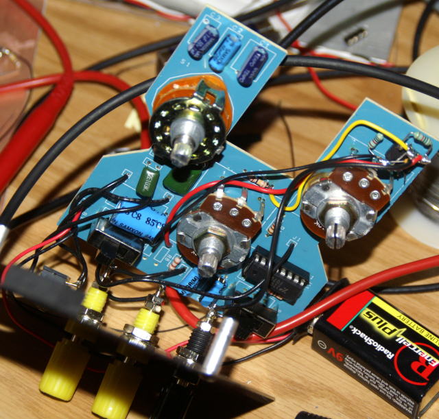
Next, I superglued the OPA2134 to the FG-500 circuit board. The location was a bit further from the circuits than I would have liked, but that spot was fairly open, and so was easy. I unsoldered R7, R8, and by accident, R4. I then resoldered a replacement R4. R9 and R4, by the way, act to limit the XR2206's gain. The XR2206 has a different peak-to-peak amplitude, for the same impedence, with triangle waves than with sine waves, and R9 and R4 attempt to compensate for that.
Finally, I soldered wires to the power supply of the OPA2134. These are best gotten from the old holes for R7 and R8. I connected the soldered a wire to connect the output of the OPA2134 to the hole left by R8. Finally, I soldered a wire from the ground binding post to the output of the OPA2134. I would have been better off running this to the last hole left by R7, but I didn't think of it at the time. The final box, open, is shown below (closed, it looks identical to an unmodified fg500):
The voltage offset is set by the DC voltage on pin 3 of the XR2206, while the amplitude of the waveform is set by the resistance to pin 3. In the original circuit, the DC voltage is set by the resistive divider R7 and R8. If the case ground reference was also set by that voltage divider, we'd be set. Unfortunately, the voltage divider is high impedence, so we could not place any load on the function generator. As a result, we buffer the voltage on the voltage divider. Once we've buffered the voltage, we might as well also use the buffered voltage in the circuit proper, since it ought to be better than a voltage divider with a capacitor.
Why not capacitors? An alternative solution might be to use an RC high pass filter to remove DC offset. This poses many problems for the ways I want to use the circuit, mostly in that this would either impact the low-frequency response of the circuit (small RC time constant), or require a large resistor to ground in the filter. A large resistor to ground would mean that what I plug the function generator into could excessively adversly impact its DC behavior (for many applications, it would no longer float properly).
The remaining issues are comperatively minor. There is a minor glitch at the top and bottom of the sine waveform, presumably as the circuit switches sides of the square wave and slopes of the triangle wave. The sine wave is only moderately sineish. The maximum output amplitude is 1V peak-to-peak (presumably, the 3V spec is running from an 18V supply). The amplitude of the output falls of dramatically by 1MHz.
Overall, however, all of the above issues are manageable, and it is a useful piece of equipment. It buys 90% of the benefit of a precision function generator, at 10% of the price.
I did this around a half-decade ago. Looking at it, if I were to do it again, I'd either:
I believe I did not do #2 since I was using this at extremely low frequencies where feedback would reduce gain and hurt waveform shape. I did not do #1 since I didn't have an appropriate pot on hand the day I needed it.