xcircuit source
Many years ago, I competed in MASLab, an MIT competition to build an autonomous robot. A year or two after that, I was on the MASLab staff, helping prepare the hardware for the year's competition. One of the projects I worked on was an optical encoder. This optical encoder was somewhat unique in that it was designed to be very robust (or at least substantially better than the disaster that most hobbyist designs are). It worked under a wide range of lighting conditions. The disk could be anywhere from a couple of millimeters to several inches from the optical elements. The pattern on the disk could be printed on a wide range of printers. It was also designed to be very inexpensive, and easy to build (very few parts to solder). It was not designed to have particularly high resolution. To achieve these goals, I used a differential design, where the encoder looked at two patterns, and compared which was brighter, rather than just looking at a single pattern. This made the encoder insensitive to ambient light level, as well as to the darkness/lightness of the pattern on the disc (which varies quite a bit, depending on choice of printer and ink).
In late 2005, I received an e-mail from a student at another university asking for my design. The student mentioned that there weren't much information on the Internet about creating optical encoders, so I figured having my ready-made design up might be useful, and as a result, I made this page.
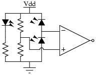
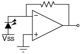
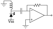
The circuit used was:
Here, the LED on the left and the resistor act as the light source. The pair of resistors in the middle give a voltage of 2.5V (assuming a 5V supply). The two photodiodes (or phototransistors) act as a voltage divider. If one sees more light than the other, it pulls to ground.
There are a number of possible improvements if one is less concerned about ease-of-assembly (this was going to be assembled by large numbers of undergrads as part of an already complex robotics project). An improved circuit would have added Schmidtt triggering to guarantee smooth transitions, as well as a low-pass filter on the output.
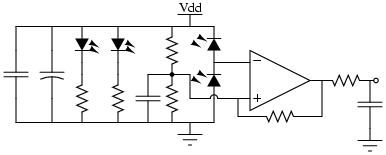
I chose the simpler design primarily in order to reduce the amount of soldering students had to do.
One more step up, the resistive divider would be replaced with a potentiometer, so that the user could tune for mismatch between photosensors.
In addition, I have a fairly flexible PostScript file that can generate disks for optical encoders. It is easy to modify it for different sizes, regular, quad-phase, single-ended, differential, and other designs. I based it off of someone else's optical encoder PostScript file (for generating simple single-phase disks), but it was adequately long ago that I no longer recall whose (I feel pretty bad, since I should really reference him or her):
The parts we used aren't very important, but for reference:
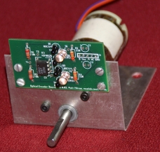
I made a PCB out of this. I had an old version, where some of the holes for the parts were not big enough. I believe the current version is this: tar/gz-compressed ZIP-compressed, but I would verify it prior to use. The pcb was designed using the free PCB package. This was my first PCB design. Our fab didn't handle circles properly in the Gerber file, so I needed to modify the source of PCB to output approximations of circles made out of lines.
The alignment of the disk with the sensors is critical.
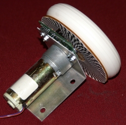
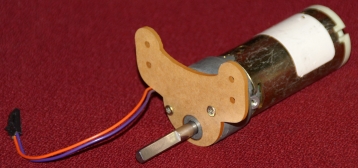
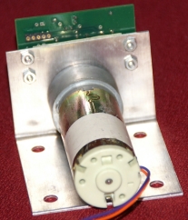
The other contest organizers provided a motor and a bracket for
mounting the motor on the robot. That bracket had holes, to which the
encoder PCB mounted. The larger versions of this image are useful for
seeing the encoder PCB:
[Larger
image]
The complete system:
[Larger image]
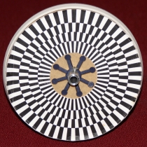
The encoder pattern was mounted on the wheel by gluing it onto a
laser-cut plastic disk that would pressure-fit on the wheel. I
designed this disk (and made the one in the photo). Students had
access to a laser cutter, so could make their own similar disks. The
centering of the laser-printed pattern on the plastic disk is
essential to proper operation:
[Larger image]
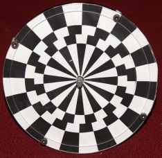
This was an alternative, plastic mount for the disk (also
laser-cut, also designed by me):
[Larger image]
A sample laser-cut wheel not attached to a motor:
[Larger image]
An image of the system from the back. There was one rear-mounted
component -- a header connector for taking the signals out. This could
be front-mounted as well, in theory, but rear-mounting makes cable
routing much easier:
[Larger image]
If you are familiar with optical encoders, skip this section.
An optical encoder measures how far something has moved, optically. It does this by looking at a pattern of alternating black-and-white, and counting number of transitions.
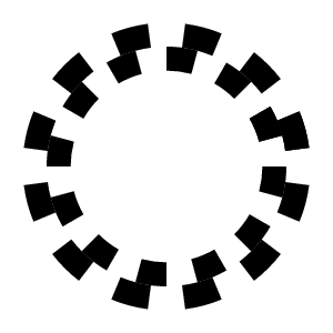
Optical encoders come in two varieties: regular and quadrature phase. A regular encoder uses a simple pattern of black-white. It can count number of transitions, but cannot tell the direction of motion:

In contrast, quadrature phase uses two staggered patterns, so that the system can tell which way the thing is turning. This can either be done explicitly with two patterns, or implicitly by using one pattern, but appropriately spaced sensors. An example of a two-pattern disk:
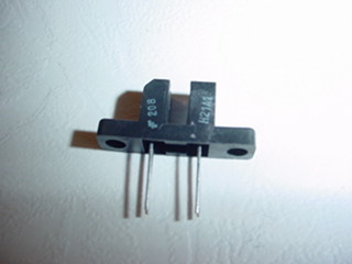
In addition, optical encoders can use one of two types of sensors: reflective and break-beam. Break-beam tend to be more accurate, but require precise mechanical alignment, sometimes hard to achieve in hobbyist projects:
In contrast, a reflective sensor just consists of an LED next to a matched photosensor (photodiode or phototransistor).
A typical optical encoder will either use a break-beam sensor, or a single pattern (dual for quad-phase) of alternating black and white. This is done because most designs are in a well-controlled environment, where there are reasonably well known, fixed levels for dark and light. In this case, we had a far less controlled environment:
For these reasons, traditional hobbyist optical encoders tend to be complete disasters. To mitigate some of these problems, we used a differential design. In so much as the photosensors matched, so that the design was very insensitive to ambient light level, or how much light was reflected from the surface, so long as different amounts of light were reflected.
Using the phototransistors back-to-back as a voltage divider (rather than amplifying first) let the design to have a huge dynamic range.
The major disadvantage of the differential design was decreased resolution. We needed four rings for a quad-phase design, instead of two. As a result, the inner-most ring was on a much smaller radius, and so could not have very dense stripes. In addition, the photosensors needed to be reasonably well matched.
You can buy packages containing a matched transmitter and receiver. These are usually only available in SMT, but are much more convenient. They come in both reflective and break-beam versions. Some are just the transmitter/receiver pair, but some include a complete circuit that can, assuming some minimum rate of rotation, self-tune itself.
The traditional photosensor design is:
A slightly better design, if you know some minimum rate of rotation, is:
This would be typically be followed up by a second stage consisting of a low-pass filter and a Schmidtt-trigger to clean up the signal.
There is one more simple way to get an optical encoder for hobbyist projects -- use a computer mouse. Plenty of household electronic devices include optical encoder (my old, broken CD-changer had at least 3 or 4), but mice are:
The disadvantage is that, in contrast to a normal optical encoder, some PS/2 mice may integrate error over long periods of time. As a result, while they work very well for sensing speed, they do not work as well for sensing position in a long-running application.
I was not around during the competition, so I do not know how well they performed in the field, or what the problems, if any, were. I initially heard from the contest organizers that the design was working very well. Later, a former student told me that some number of students having significant problems with getting reliable readings. I do not know how common problems were, but I would suspect the dominant problems would have been related to:
The version I had in my lab was extremely reliable. Without bypass capacitors, it could still tolerate a 1V sine wave on the power rail at an arbitrary frequency. It could work if the disk was as close to the sensors as possible without touching, as well as half a foot from the sensors. It could work in the dark, as well as with a bright light shining directly at the disk.
I received an e-mail about a clever hobbyist single-track absolute encoder. This design uses a single track, instead of 2-4 tracks, and scatters the sensors linearly around the disk.
The downside is that this is substantially more complex than mine:
It is also physically much bigger. The breakbeam sensors take space on both sides of the disc, so the disc cannot just be glued to a wheel. In his design, they also go all the way around the disc, so the aparatus is quite large (although this isn't a fundamental limitation -- the same pattern could be repeated 4 times around the disc, and then the sensors would fit in one quadrant of the disk).
The major upside is that you have breakbeam sensing, which is much more accurate than reflective. In addition, you can use the full outer radius of the disc, whereas the differential quadrature requires you to have an inner track that is a ways into the disc. As a result, you can get much higher resolution. A minor upside is that his page is much nicer than mine, and his instructions are somewhat more detailed.